


We contribute to “PACPT” improvements being addressed by the semiconductor industry.
The semiconductor industry is committed to improving throughput (Performance-up), space-saving (Area), and cost reduction (Cost) of manufacturing equipment. In addition, greater effort is now focused on energy-saving toward carbon neutrality (Power reduction) and shortening delivery times for manufacturing equipment with requirements for handling increasingly sophisticated and complicated processing including die shrink and multilayering (Time to market), and it is expected that overall investment will likewise increase in order to meet the needs for semiconductors that are essential for all industrial products necessary for daily life.
-

Performance-up (Improvement in technology, performance, and throughput)
Throughput improvement means increasing the number of wafers taken out from the equipment per hour. Our robots can contribute to improvements in throughput by speeding up transfer.
Applicable solutions:SOLUTION 01 SOLUTION 02 SOLUTION 03
-
Area reduction
Area reduction means minimizing the installation areas occupied by equipment front end modules (EFEMs), vacuum transfer modules (VTMs), and processing machines/equipment (PMs). SCARA robot transfers contribute to customer needs for space-saving.
Applicable solutions:SOLUTION 04
-

Cost reduction
Cost reduction means improving productivity per unit area, which is related to throughput improvement and space-saving.
Applicable solutions:SOLUTION 05
-

Power reduction
Power reduction means reducing power consumption by reducing robot weight, eliminating the use of speed reducers that result in large energy loss, and sharing servo driver power supply that uses regenerative energy for other axes.
Applicable solutions:SOLUTION 06
-

Time to market
Time to market means realizing customer requests for shorter delivery times by module production of robot components, which also contributes to cost reductions.
Applicable solutions:SOLUTION 05
In order to contribute to improvements in performance and throughput in line with trends in the semiconductor industry, we pursue lower vibration, higher speeds, and higher wafer transfer precision. In addition, we continue to add space-saving clean transfer robots to our lineup.
Basic Configuration
The basic configuration of standard wafer transfer systems installed in semiconductor factories and the basic configuration of clean transfer robots that play an important role in such systems are shown below.
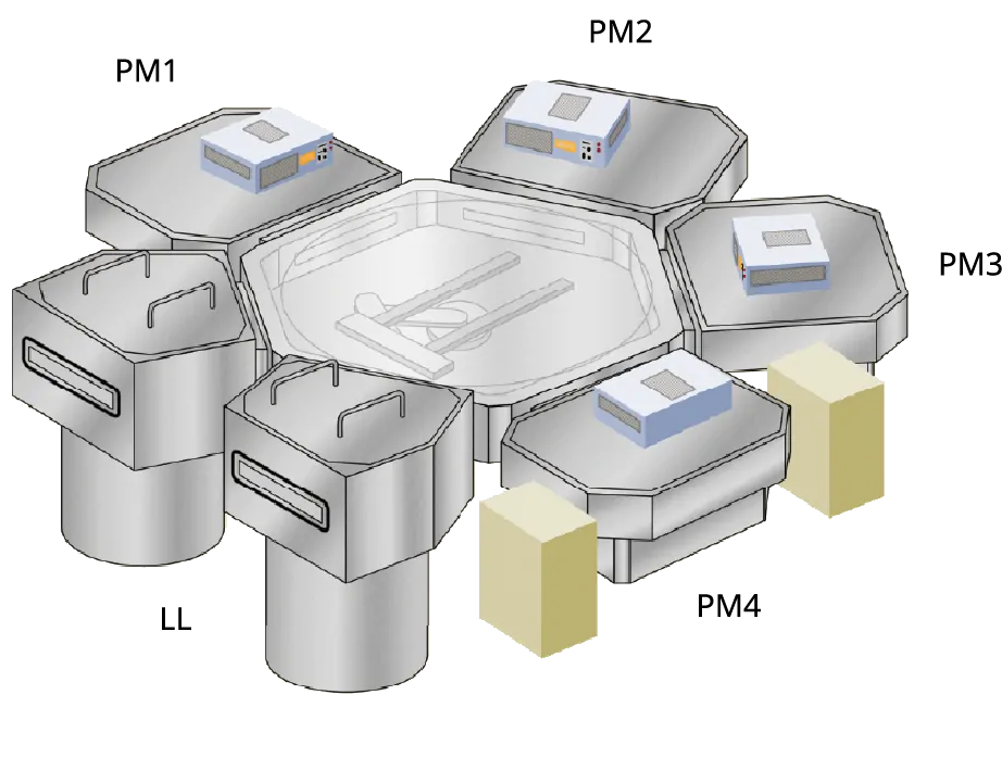
Basic Configuration of Wafer Transfer System
Wafers are transferred to process chambers, and are returned to their original slot positions in the FOUPs after completion of processing by using an EFEM equipped with a clean robot for atmospheric environment and a wafer aligner, and a vacuum transfer module equipped with a clean robot for vacuum environment.

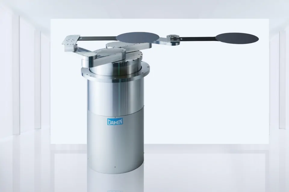
Basic Configuration of Clean Transfer Robot
A robot is basically configured with a body, controller, teach pendant, and control cable, while a hand (end effector) and primary power supply cable are optional.

Introduction to Solutions
-

Realizes the world’s fastest level of high-precision transfer under vacuum environments.

-

Realizes lower vibration that reduces the risk of particle generation.
-

Significantly simplifies teaching work and reduces work hours.
-

Reduces the installation area of vacuum process equipment by adopting SCARA arm type vacuum robot.

-

Realizes cost reductions and shorter delivery times by module production of robot components.


-

Realizes energy-savings by sharing servo driver power supply.

DAIHEN’s clean transfer robots are mounted at the transfer system section of semiconductor manufacturing equipment to enhance performance, including high speed, high precision, high payload, and low vibration, and also offer space-saving and energy-saving features that contribute to the development of the semiconductor industry.
We released a vacuum robot that achieves the industry’s fastest transfer level (650WPH), making a significant contribution to improvements in semiconductor productivity.
Semiconductor wafer transfer robot “UT-VDW3000” realizes the world’s fastest level of high-speed transfer
For the UT-VDW3000, direct drive motors is mounted on the robot arm and the rotation
axis, and steel belts and high-friction pads are adopted for the transmission of arm
extension/retraction and on the hands.
By significantly reducing vibration when the robot is operating at high speed and
suppressing wafer slippage to the minimum extent, the world’s fastest level of
high-speed transfer at “650WPH*” has been realized under vacuum environments.
The higher-speed wafer transfer contributes to improvements in semiconductor
productivity.
*The number of wafers processed per hour is 650.
High-speed wafer removal and storage between two stages.
- A pre-processing wafer is removed from the wafer delivery stage in front and a processed wafer is placed simultaneously.
- After placement, while the arm is retracted to the HOME position, the rotation axis and ascending/descending axis are operated at the same time toward the processing stage in the rear.
- Upon arriving at the front of the processing stage, the arm extends to remove the processed wafer and place the pre-processing wafer simultaneously.
- After placement, while the arm is retracted to the HOME position, the rotation axis and ascending/descending axis are operated at the same time toward the wafer delivery stage in front, and then, the same operations are repeated.
Reduced vibration of vacuum transfer robots suppresses particle generation and contributes to improvements in the yield of semiconductor miniaturization processes.
If vibration is transmitted to an end effector during wafer transfer, the risk of particle generation between the end effector and wafers increases. Since the adhesion of particles to wafer surfaces affects yields, we are working to further reduce vibration in order to reduce such risk.
Adoption of direct motors without using gears to eliminate vibration source

A speed reducer connected with a small servomotor can increase the power output, but vibration occurs when the gears are engaged during rotating operation. The amount of vibration may not pose a problem when general objects are gripped and transferred, but it will cause problems during wafer transfer in vacuum, such as wafer slippage and particle generation. Therefore, for wafer transfer in vacuum, driving only with a motor without using a speed reducer leads to significant reduction in vibration.
Vibration comparison between models with/without a speed reducer
In a vacuum robot, if vertical vibration is transmitted to wafers during operation,
frictional force will be lost, and the wafers will easily slip. On a robot equipped
with a speed reducer, vertical vibration occurs due to the engagement of the gears
during operation.
However, a robot equipped with a direct drive motor that secures the torque required
to drive the robot requires no speed reducer and no vertical vibration occurs,
though the size of the drive source becomes large.
■Measurement chart of
vertical vibration on
the hand on which wafers
are placed during robot operation

Structurally, the control command interface dedicated to semiconductor wafer transfer and simple teaching operation are user-friendly even for first-time users.
Significant simplification of teaching work reduces work hours.
The accessing target of an object transferred is a FOUP in which multiple wafers are stored or the stage on which one wafer is placed. Teaching work of the target stage is simply performed by one point, and even when the target is a FOUP, teaching work can be completed by only a few points.
Teaching points of the target station are reduced from 5 to 1.
For placing/removing wafers into/from process equipment, there are five transfer points (RB, EB, EM, ET, and RT).
【Robot motion in vacuum】
・Removing a wafer: RB → EB (arm extension) → EM (the Z-axis ascends to the wafer
contact position) → ET
(the Z-axis further ascends to the position where the wafer is lifted up completely) →
RT (arm retraction to the HOME position)
・Storing the wafer: Implement the removing operation in reverse order(RT
› ET › EM › EB ›
RB)

● Problem in teaching work
- ・With standard robot controllers, teaching is performed on all five points (RB, EB, EM, ET, and RT).
- ・There are also cases where teaching is performed on intermediate positions between RB and EB and between ET and RT.
→ There is a problem that teaching work requires a significant amount of time.
● Countermeasures
- ・ The developed vacuum robot is a cylindrical coordinate type, and the arm extension/retraction stroke and the positions of the rotation axis (θ-axis) and the ascending/descending axis (Z-axis) are fixed by teaching the transfer position (EM).
- ・For the amount of the Z-axis ascent from EB to EM, which is pre-registered by parameters, no teaching work is required.
- ・Similarly, no teaching work is required for EM → ET.
- ・For ET → RT, a simple return is made on the arm axis (R-axis) to the HOME position, and no teaching work is required.
 Actual teaching work
・Move the arm into the process equipment and simply perform teaching work at the EM position.
The teaching position in the cylindrical coordinate system is EM (R, θ, Z). Assuming that the amount of the Z-axis ascending/descending in the process equipment is α, other teaching points are EB (R, θ, Z-α), ET (R, θ, Z+α), RB (0, θ, Z-α), and RT (0, θ, Z+α).
・Teaching work is reduced as it is completed in only one place per process equipment.
Control command interface dedicated to semiconductor wafer transfer
Wafers are transferred by the motion commands sent from the robot-mounted process equipment
controller to the robot controller.
Between the process equipment controller and robot controller, serial communication via a
LAN is commonly used.
For operating the robot, the content of serial communication messages is defined.
Rules in the table below are set to determine whether to remove or store wafers, at which
station, in which slot, and with which arm to execute commands.
| Motion command | Station position | Slot position | Arm selection | ||||
|---|---|---|---|---|---|---|---|
| No. | Details | No. | Details | No. | Details | No. | Details |
| 0001 | HOME | 0001 | Set by user | 0001 |
The bottom row is the first slot |
0001 | Left hand |
| 0002 | GET | : | : | 0002 | Right hand | ||
| 0003 | PUT | 0008 | 0025 | ||||
※While some examples of motion commands are shown above, fragmented motion commands are also prepared.
Definition of the message format
The format of messages sent via a LAN is defined in the order of motion command no. at the head, station no., slot no., and arm selection.
Motion (1): When the following message is sent from the equipment to the robot side, the robot performs the motion to get a wafer in the first slot of station no. 5 with the right hand.

Motion (2): By the execution of the following message, a wafer is placed in the first slot of station no. 5 with the left hand, and replacement of wafers is completed.

■Details of the motion performed when each command is executed
Motion (1): The θ-axis and Z-axis move to the RB position of the right hand of station no. 5. After that, the arm extends to the EB position, and the Z-axis ascends to EM and further to ET. Finally, the arm retracts to the RT position, when the motion of the command is finished.
Motion (2): The θ-axis and Z-axis move to the RT position of the left hand of station no. 5. After that, the arm extends to the ET position, and the Z-axis descends to EM and further to EB. Finally, the arm retracts to the RB position, when the motion of the command is finished.
Realizes reductions in power loss and vibration by adopting a DD motor, and the installation area of equipment can be reduced by adopting a SCARA arm type robot and square formation of vacuum chambers.
Conventional cylindrical coordinate type
(Cluster formation)
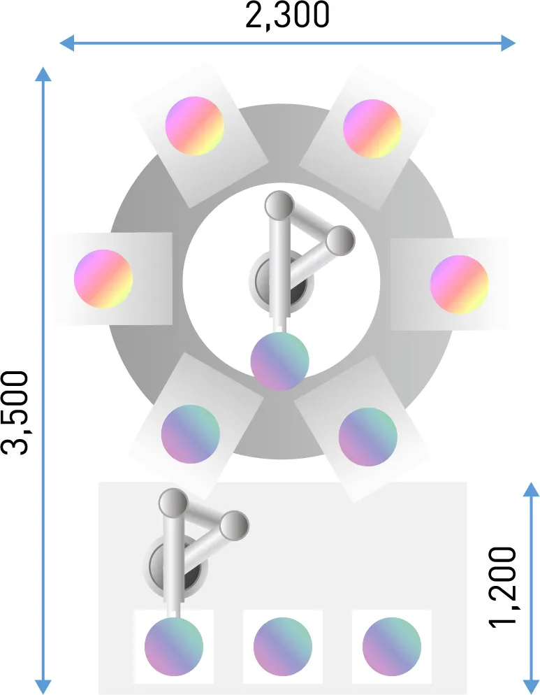
SCARA arm type
(Square formation)
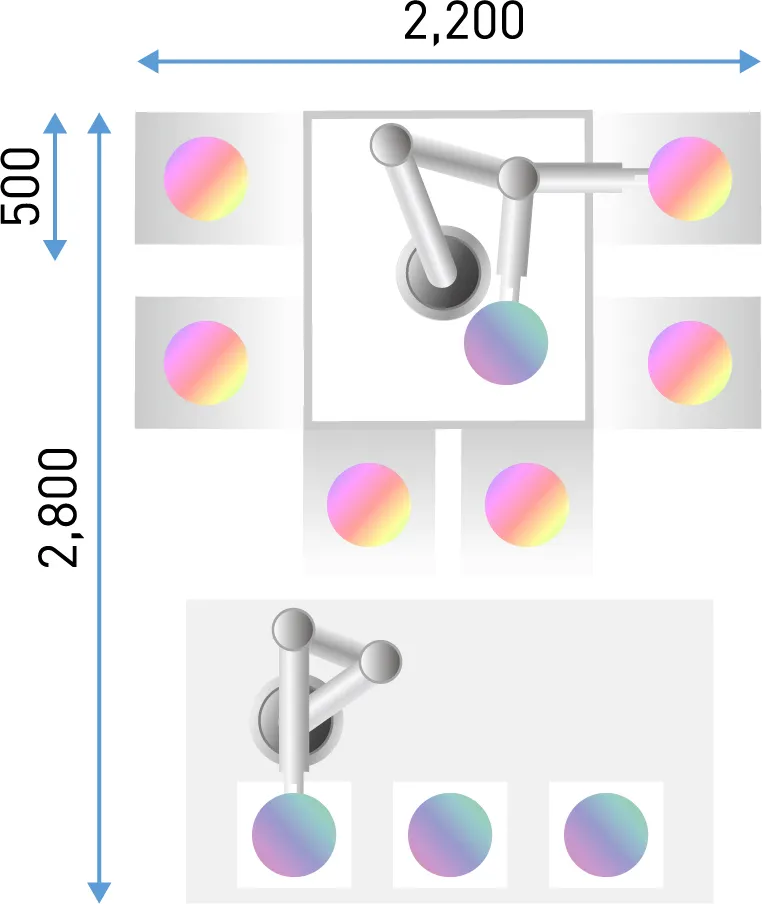


In the field of semiconductor processing, there is a trend toward expanding the clean room
area because more process equipment is required due to die shrink and multilayering.
In order to solve this problem, we propose to shift vacuum transfer equipment from cluster
formation to square formation.
Currently, a cylindrical coordinate type robot is used in cluster formation that makes
movements of the robot arm easy to understand, but the footprint of the vacuum equipment
becomes larger due to circular transfer module. By changing cluster formation to square
formation and using a SCARA arm type robot to transfer wafers, the footprint of the vacuum
equipment can be reduced.
Realizes cost reductions and shorter delivery times by modularizing the production of robot components and combining various modules according to respective customer needs.

Realizes shorter delivery times by reduced wiring type wafer transfer robot
A reduced wiring type wafer transfer robot is a robot in which each component of the
robot is modularized by superimposing various signals on the control power supply
using high-speed power line communication.
Realization of the shortest delivery time of 45 days by assembling each module into
a finished robot.

■ Each module

The specification checklist includes each module.
By selecting and ordering each module, a robot according to your needs can be created.
In addition to modules in the specification checklist, we offer various modules that can be
selected from among 16 types for even a single robot body. “Arms,” “hands,” “hand bases,”
etc., can also be selected.
*Inquiry required
Realizes energy-savings by sharing servo driver power supply.

We replaced a single-axis servo driver (former controller) with a multi-axis servo driver (new controller) for our long-selling machines. With this new servo driver, the regenerative energy generated during deceleration motion can be consumed on other axes, which was dissipated as heat by the regenerative resistor previously, and primary power consumption is suppressed, realizing energy-savings.
